Abstract
Lithium-ion batteries (LIBs) are considered to be one of the most important energy storage technologies. As the energy density of batteries increases, battery safety becomes even more critical if the energy is released unintentionally. Accidents related to fires and explosions of LIBs occur frequently worldwide. Some have caused serious threats to human life and health and have led to numerous product recalls by manufacturers. These incidents are reminders that safety is a prerequisite for batteries, and serious issues need to be resolved before the future application of high-energy battery systems. This Review aims to summarize the fundamentals of the origins of LIB safety issues and highlight recent key progress in materials design to improve LIB safety. We anticipate that this Review will inspire further improvement in battery safety, especially for emerging LIBs with high-energy density.
THE ORIGINS OF LIB SAFETY ISSUES
The organic liquid electrolyte inside LIBs is intrinsically flammable. One of the most catastrophic failures of a LIB system is the cascading thermal runaway event, which is considered the main cause of battery safety concerns . In general, thermal runaway occurs when an exothermic reaction goes out of control. As the temperature of the battery rises to above ~80°C, the exothermic chemical reaction rate inside the batteries increases and further heats up the cell, resulting in a positive feedback cycle . The continuously rising temperatures may result in fires and explosions, especially for large battery packs. Therefore, understanding the causes and processes of thermal runaway can guide the design of functional materials to improve the safety and reliability of LIBs. The thermal runaway process can be divided into three stages, as summarized in Fig. 1.

Fig. 1 Three stages for the thermal runaway process.
Stage 1: The onset of overheating. The batteries change from a normal to an abnormal state, and the internal temperature starts to increase. Stage 2: Heat accumulation and gas release process. The internal temperature quickly rises, and the battery undergoes exothermal reactions. Stage 3: Combustion and explosion. The flammable electrolyte combusts, leading to fires and even explosions.
The onset of overheating (stage 1)
Thermal runaway starts from the overheating of the battery system. The initial overheating can occur as a result of the battery being charged beyond the designed voltage (overcharging), exposure to excessive temperatures, external short circuits due to faulty wiring, or internal short circuits due to cell defects. Among them, internal shorting is the predominant reason for thermal runaway and is relatively hard to control. Internal shorting can happen in circumstances of cell crush such as external metal debris penetration; vehicle collision; lithium dendrite formation under high current density charging, under overcharging conditions or at low temperatures; and flawed separators created during battery assembly, to name a few. For example, in early October 2013, a Tesla car near Seattle hit metal debris that pierced the shield and the battery pack. The debris penetrated the polymer separators and directly connected the cathode and anode, causing the battery to short-circuit and to catch fire ; in 2016, the Samsung Note 7 battery fires were due to the aggressively ultrathin separator that was easily damaged by outside pressure or the welding burrs on the positive electrode, causing the battery to short-circuit .
During stage 1, battery operation changes from a normal to an abnormal state, and all the issues listed above will cause the battery to overheat. When the internal temperature starts to increase, stage 1 ends and stage 2 begins.
Heat accumulation and gas release process (stage 2)
As stage 2 begins, the internal temperature quickly rises, and the battery undergoes the following reactions (these reactions do not occur in the exact given order; some of them may occur simultaneously):
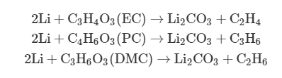
(1) Solid electrolyte interphase (SEI) decomposition due to overheating or physical penetration . The SEI layer mainly consists of stable (such as LiF and Li2CO3) and metastable [such as polymers, ROCO2Li, (CH2OCO2Li)2, and ROLi] components. However, the metastable components can decompose exothermically at roughly >90°C, releasing flammable gases and oxygen. Take (CH2OCO2Li)2 as an example
(CH2OCO2Li)2→Li2CO3+C2H4+CO2+0.5O2
(2) With the decomposition of SEI, the temperature builds up, and the lithium metal or intercalated lithium in the anode will react with the organic solvents in the electrolyte, releasing flammable hydrocarbon gases (ethane, methane, and others) . This is an exothermic reaction that drives the temperature up further.
(3) When T > ~130°C, the polyethylene (PE)/polypropylene (PP) separator starts to melt, which further deteriorates the situation and causes a short circuit between the cathode and the anode.
(4) Eventually, heat causes the decomposition of the lithium metal oxide cathode material and results in release of oxygen . Take LiCoO2 as an example, which can decompose starting at ~180°C as follows
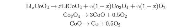
The breakdown of the cathode is also highly exothermic, further increasing the temperature and pressure and, as a result, further speeding up the reactions.
During stage 2, the temperature increases and oxygen accumulates inside batteries. The thermal runaway process proceeds from stage 2 to stage 3 as soon as enough oxygen and heat have accumulated for battery combustion.
Combustion and explosion (stage 3)
At stage 3, combustion starts. The electrolytes of LIBs are organic, which are almost universal combinations of cyclic and linear alkyl carbonates. They have high volatility and are intrinsically highly flammable. Taking the popularly used carbonate electrolyte [the mixture of ethylene carbonate (EC) + dimethyl carbonate (DMC) (1:1 by weight)] as an example, it exhibits a vapor pressure of 4.8 kPa at room temperature and an extremely low flash point of 25° ± 1°C at an air pressure of 1.013 bar . The released oxygen and heat in stage 2 provide the required conditions for the combustion of flammable organic electrolytes, thereby causing fire or explosion hazards.
In stages 2 and 3, the exothermic reactions happen under near-adiabatic conditions. Thus, accelerated rate calorimetry (ARC) is a widely used technique that simulates the environment inside the LIBs, which facilitates our understanding of the thermal runaway reaction kinetics. Figure 2 shows a typical ARC curve of a LIB recorded during the thermal abuse tests . Simulating the temperature increases in stage 2, an external source of heat increases the battery temperature to the onset temperature. Above this temperature, the SEI decomposes, which will trigger more exothermic chemical reactions. Eventually, the separator will melt. The self-heating rate will increase afterward, leading to thermal runaway (when the self-heating rate is >10°C/min) and electrolyte combustion (stage 3).

The anode is mesocarbon microbead graphite. The cathode is LiNi0.8Co0.05Al0.05O2. The electrolyte is 1.2 M LiPF6 in EC/PC/DMC. A Celgard 2325 trilayer separator was used. Adapted with permission from Electrochemical Society Inc.
It should be noted that the reactions illustrated above do not strictly happen one after another in the given order. They are, rather, complex and systematic issues.
MATERIALS WITH IMPROVED BATTERY SAFETY
Based on the understanding of battery thermal runaway, many approaches are being studied, with the aim of reducing safety hazards through the rational design of battery components. In the succeeding sections, we summarize different materials approaches to improving battery safety, solving problems corresponding to different thermal runaway stages.
To solve the problems in stage 1 (the onset of overheating)
Reliable anode materials. The Li dendrite formation on the anode of LIB initiates the first stage of thermal runaway. Although this issue has been alleviated in the anodes of commercial LIBs (for example, carbonaceous anodes), Li dendrite formation has not been entirely inhibited. For example, in commercial LIBs, dendrite deposition occurs preferentially at graphite electrode edges if the anodes and cathodes are not well paired . In addition, the improper operation conditions of the LIBs can also result in Li metal deposition with dendrite growth. It is well known that dendrite can be easily formed if the battery is charged (i) at high current densities where the deposition of Li metal is faster than the diffusion of Li ions in the bulk graphite ; (ii) under overcharging conditions when graphite is overlithiated; and (iii) at low temperatures [for example, subambient temperature (~0°C)], due to the increased viscosity of the liquid electrolyte and the increased Li-ion diffusion resistance .
From the point of view of materials properties, the root origin determining the onset of Li dendrite growth on the anode is the unstable and nonuniform SEI, which causes uneven local current distribution . Electrolyte components, especially additives, have been investigated to improve SEI uniformity and eliminate Li dendrite formation. Typical additives include inorganic compounds [for example, CO2 , LiI , etc.] and organic compounds containing unsaturated carbon bonds such as vinylene carbonate and maleimide additives; unstable cyclic molecules such as butyrolactone , ethylene sulfite , and their derivatives; and fluorinated compounds such as fluoroethylene carbonate , among others. Even at the parts-per-million level, these molecules can still improve the SEI morphology, thus homogenizing the Li-ion flux and eliminating the possibility of Li dendrite formation.
Overall, the Li dendrite challenges are still present in graphite or carbonaceous anodes and silicon/SiO containing next-generation anodes. Solving the issue of Li dendrite growth is a challenge that is critical for the adaptation of high-energy density Li-ion chemistries in the near future. It should be noted that, recently, considerable efforts have been devoted to solving the issue of Li dendrite formation in pure Li metal anodes by homogenizing the Li-ion flux during Li deposition; for example, protective layer coating , artificial SEI engineering , etc. In this aspect, some of the methods could possibly shed light on how to tackle the issue on carbonaceous anodes in LIBs as well.
Multifunctional liquid electrolytes and separators. The liquid electrolyte and separator play key roles in physically separating the high-energy cathode and anode. Thus, well-designed multifunctional electrolytes and separators can significantly protect the batteries at the early stage of battery thermal runaway (stage 1).
To protect batteries from mechanical crushing, a shear thickening liquid electrolyte has been obtained by the simple addition of fumed silica to carbonate electrolyte (1 M LiFP6 in EC/DMC) . Upon mechanical pressure or impact, the fluid exhibits a shear thickening effect with an increase in viscosity, therefore dissipating the impact energy and demonstrating tolerance to crushing (Fig. 3A)
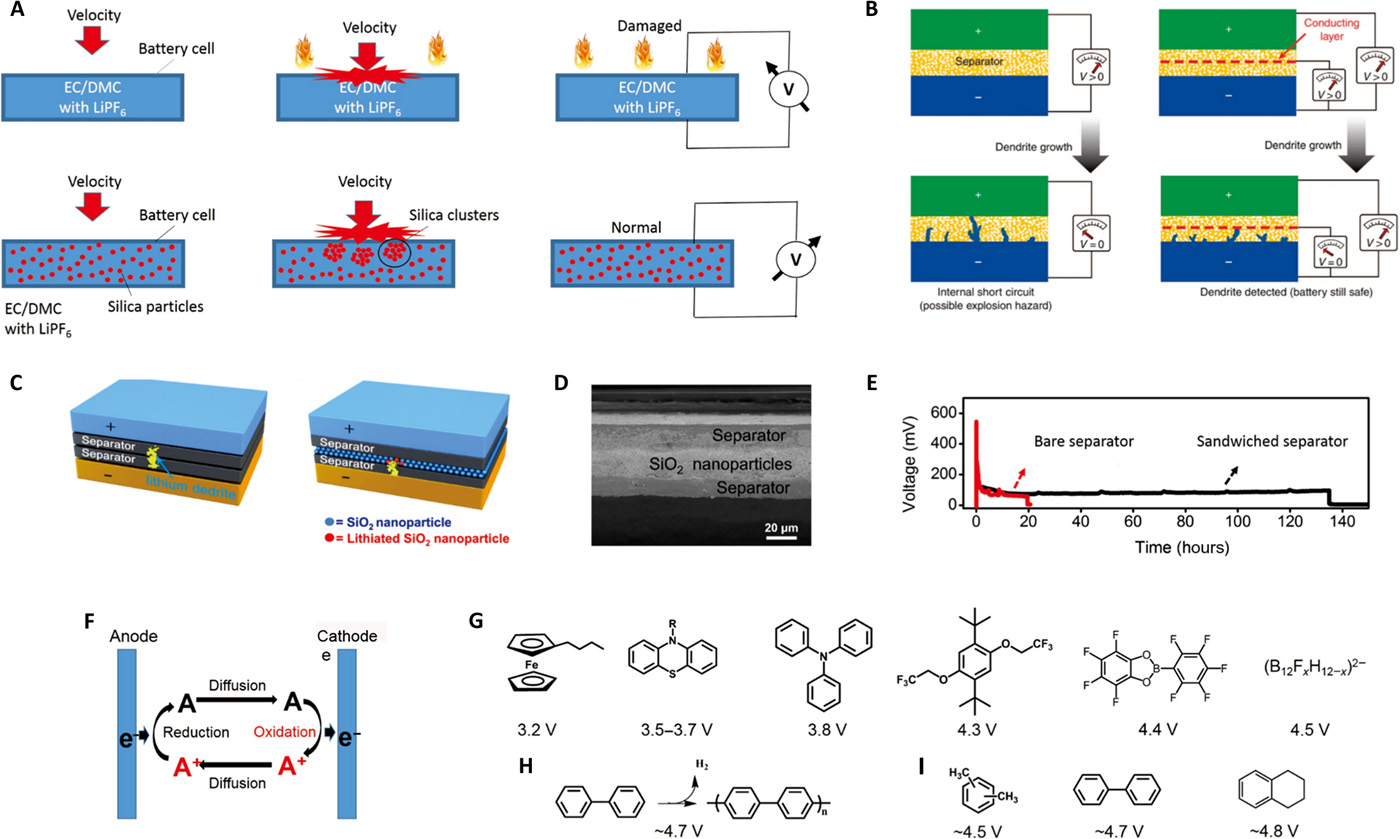
Fig. 3 Strategies to solve the issues in stage 1.
(A) Shear thickening electrolyte. Top: For normal electrolyte, mechanical impact can lead to battery internal shorting, causing fires and explosions. Bottom: The novel smart electrolyte with shear thickening effect under pressure or impact demonstrates excellent tolerance to crushing, which could significantly improve the mechanical safety of batteries. (B) Bifunctional separators for early detection of lithium dendrites. Dendrite formation in a traditional lithium battery, where complete penetration of the separator by a lithium dendrite is only detected when the battery fails because of an internal short circuit. In comparison, a lithium battery with a bifunctional separator (consisting of a conducting layer sandwiched between two conventional separators), where the overgrown lithium dendrite penetrates the separator and makes contact with the conducting copper layer, resulting in a drop in VCu−Li, which serves as a warning of impending failure due to an internal short circuit. However, the full battery remains safely operational with nonzero potential. (A) and (B) are adapted or reproduced with permission from Springer Nature. (C) Trilayer separator to consume hazardous Li dendrites and extend battery life. Left: Lithium anodes can easily form dendritic deposits, which can gradually grow bigger and penetrate the inert polymer separator. When the dendrites finally connect the cathode and anode, the battery is short-circuited and fails. Right: A layer of silica nanoparticles was sandwiched by two layers of commercial polymer separators. Therefore, when lithium dendrites grow and penetrate the separator, they will contact the silica nanoparticles in the sandwiched layer and be electrochemically consumed. (D) Scanning electron microscopy (SEM) image of the silica nanoparticle sandwiched separator. (E) Typical voltage versus time profile of a Li/Li battery with a conventional separator (red curve) and the silica nanoparticle sandwiched trilayer separator (black curve) tested under the same conditions. (C), (D), and (E) are reproduced with permission from John Wiley and Sons. (F) Schematic illustration of the mechanisms of the redox shuttle additives. On an overcharged cathode surface, the redox additive is oxidized to the form [O], which subsequently would be reduced back to its original state [R] on the surface of the anode by diffusion through the electrolyte. The electrochemical cycle of oxidation-diffusion-reduction-diffusion can be maintained indefinitely and hence locks the cathode potential from hazardous overcharging. (G) Typical chemical structures of the redox shuttle additives. (H) Mechanism of the shutdown overcharge additives that can electrochemically polymerize at high potentials. (I) Typical chemical structures of the shutdown overcharge additives. The working potentials of the additives are listed under each molecular structure in (G), (H), and (I).
Separators can electronically insulate the cathode and anode and play an important role in monitoring the health condition of a battery in situ to prevent further deterioration past stage 1. For example, a “bifunctional separator” with a polymer-metal-polymer trilayer configuration (Fig. 3B) can provide a new voltage-sensing function. When a dendrite grows out and reaches the intermediate layer, it will connect the metal layer and the anode such that a sudden voltage drop between them can be detected immediately as an output.
Besides detection, a trilayer separator was designed to consume the hazardous Li dendrites and slow down their growth after penetrating the separator . A layer of silica nanoparticles, sandwiched by two layers of commercial polyolefin separators (Fig. 3, C and D), can consume any penetrating hazardous Li dendrites, thus efficiently improving the battery safety. The life of the protected battery was significantly extended by approximately five times compared with that having conventional separators (Fig. 3E).
Overcharging protection. Overcharging is defined as charging a battery beyond its designed voltage. Overcharging could be triggered by high specific current densities, aggressive charging profiles, etc., which can bring about a series of problems, including (i) deposition of Li metal on the anode, which seriously affects the battery’s electrochemical performance and safety; (ii) decomposition of the cathode material, releasing oxygen; and (iii) decomposition of the organic electrolyte, releasing heat and gaseous products (H2, hydrocarbons, CO, etc.), which are responsible for thermal runaway . The electrochemical reactions during the decomposition are complicated, some of which are listed below.
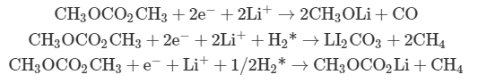
The asterisk (*) denotes that the hydrogen gas originates from the protic, leaving groups generated during the oxidation of carbonates at the cathode, which then diffuse to the anode to be reduced and generate H2.
On the basis of the differences in their functions, the overcharge protection additives can be classified as redox shuttle additives and shutdown additives. The former protects the cell from overcharge reversibly, while the latter terminates cell operation permanently.
Redox shuttle additives function by electrochemically shunting the excess charge injected into the battery when overcharge occurs. As shown in Fig. 3F, the mechanism is based on a redox additive that has an oxidation potential slightly lower than that of the electrolyte anodic decomposition. On an overcharged cathode surface, the redox additive is oxidized to the form [O], which subsequently would be reduced back to its original state [R] on the surface of the anode after diffusion through the electrolyte. Afterward, the reduced additive can diffuse back to the cathode, and the electrochemical cycle of “oxidation-diffusion-reduction-diffusion” can be maintained indefinitely and hence locks the cathode potential from further hazardous overcharging. Studies have shown that the redox potential of the additives should be about 0.3 to 0.4 V above the potential of the cathode .
A series of additives with well-tailored chemical structures and redox potentials have been developed, including organometallic metallocenes , phenothiazines , triphenylamines , dimethoxybenzenes and their derivatives , and 2-(pentafluorophenyl)-tetrafluoro-1,3,2-benzodioxaborole (Fig. 3G). By tailoring molecular structures, the additive oxidation potentials can be tuned to above 4 V, which is suitable for the rapidly developing high-voltage cathode materials and electrolytes. The basic design principle involves lowering the highest occupied molecular orbital of the additive by means of adding electron-withdrawing substitutes, leading to an increase in oxidation potential. Besides organic additives, some inorganic salts, which not only can function as the electrolyte salt but also can serve as a redox shuttle, such as perfluoroborane cluster salts [that is, lithium fluorododecaborates (Li2B12FxH12−x)], have also been found to be efficient redox shuttle additives .
Shutdown overcharge additives are a class of irreversible overcharge protection additives. They function either by releasing gas at high potentials, which, in turn, activates a current interrupter device, or by permanently electrochemically polymerizing at high potentials to terminate the battery operation before catastrophic results occur (Fig. 3H). Examples of the former include xylene , cyclohexylbenzene, and biphenyl , while examples of the latter include biphenyl and other substituted aromatic compounds (Fig. 3I). The negative effects of shutdown additives are still the long-term operation and storage performance of the LIBs because of the irreversible oxidation of these compounds.
To solve the problems in stage 2 (heat accumulation and gas release process)
Reliable cathode materials. Lithium transition metal oxides, such as layered oxides LiCoO2, LiNiO2, and LiMnO2; the spinel-type oxide LiM2O4; and the polyanion type LiFePO4, are popularly used cathode materials, which, however, have safety issues especially at high temperatures. Among them, the olivine-structured LiFePO4 is relatively safe, which is stable up to 400°C, while LiCoO2 starts to decompose at 250°C. The reason for the improved safety of LiFePO4 is that all of the oxygen ions form strong covalent bonds with P5+ to form the PO43− tetrahedral polyanions, which stabilize the entire three-dimensional framework and provide improved stability compared with other cathode materials, although there still have been some battery fire accidents reported . The major safety concern arises from the decomposition of these cathode materials at elevated temperatures and the simultaneous oxygen release, which together can lead to combustion and explosions, seriously compromising battery safety . For example, the crystal structure of the layered oxide LiNiO2 is unstable because of the existence of Ni2+, the ionic size of which is similar to that of Li+. The delithiated LixNiO2 (x < 1) tends to convert to a more stable spinel-type phase LiNi2O4 (spinel) and rocksalt-type NiO, with oxygen released into liquid electrolyte at around 200°C, leading to electrolyte combustion.
Considerable efforts have been made to improve the thermal stability of these cathode materials by atom doping and surface protective coatings.
Atom doping can significantly increase the thermal stability of the layered oxide materials due to the resulting stabilized crystal structures. The thermal stability of LiNiO2 or Li1.05Mn1.95O4 can be significantly improved by partial substitution of Ni or Mn with other metal cations, such as Co, Mn, Mg, and Al . For LiCoO2, the introduction of doping and alloying elements such as Ni and Mn can drastically increase the decomposition onset temperature Tdec, while also avoiding reactions with electrolyte at high temperatures. However, increases in cathode thermal stability in general come with sacrifices in specific capacity. To solve this problem, a concentration-gradient cathode material for rechargeable lithium batteries based on a layered lithium nickel cobalt manganese oxide has been developed (Fig. 4A) . In this material, each particle has a Ni-rich central bulk and a Mn-rich outer layer, with decreasing Ni concentration and increasing Mn and Co concentrations as the surface is approached (Fig. 4B). The former provides high capacity, whereas the latter improves thermal stability. This novel cathode material was shown to improve the safety of batteries without compromising their electrochemical performance (Fig. 4C).
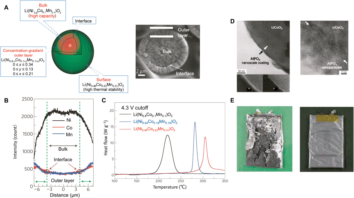
Fig. 4 Strategies to solve the issues in stage 2: Reliable cathodes.
(A) Schematic diagram of a positive electrode particle with a Ni-rich core surrounded by a concentration-gradient outer layer. Each particle has a Ni-rich central bulk Li(Ni0.8Co0.1Mn0.1)O2 and a Mn-rich outer layer [Li(Ni0.8Co0.1Mn0.1)O2] with decreasing Ni concentration and increasing Mn and Co concentrations as the surface is approached. The former provides high capacity, whereas the latter improves the thermal stability. The average composition is Li(Ni0.68Co0.18Mn0.18)O2. A scanning electron micrograph of a typical particle is also shown on the right. (B) Electron-probe x-ray microanalysis results of the final lithiated oxide Li(Ni0.64Co0.18Mn0.18)O2. The gradual concentration changes of Ni, Mn, and Co in the interlayer are evident. The Ni concentration decreases, and the Co and Mn concentrations increase toward the surface. (C) Differential scanning calorimetry (DSC) traces showing heat flow from the reaction of the electrolyte with concentration-gradient material Li(Ni0.64Co0.18Mn0.18)O2, the Ni-rich central material Li(Ni0.8Co0.1Mn0.1)O2, and the Mn-rich outer layer [Li(Ni0.46Co0.23Mn0.31)O2]. The materials were charged to 4.3 V. (A), (B), and (C) are reproduced with permission from Springer Nature. (D) Left: Transmission electron microscopy (TEM) bright-field image of the AlPO4 nanoparticle–coated LiCoO2; energy dispersive x-ray spectrometry confirms the Al and P components in the coating layer. Right: High-resolution TEM image showing the AlPO4 nanoparticles (~3 nm in diameter) in the nanoscale coating layer; the arrows indicate the interface between the AlPO4 layer and LiCoO2. (E) Left: A picture of a cell containing a bare LiCoO2 cathode after the 12-V overcharge test. The cell burned and exploded at that voltage. Right: A picture of a cell containing the AlPO4 nanoparticle–coated LiCoO2 after the 12-V overcharge test. (D) and (E) are reproduced with permission from John Wiley and Sons.
Another strategy to improve thermal stability is to coat the cathode material with a protective thin layer of thermally stable Li+ conducting compounds, which can prevent the direct contact of cathode materials with electrolyte and thus decrease side reactions and heat generation. The coatings can be either inorganic films [for example, ZnO , Al2O3, AlPO4 , AlF3 , etc.], which can conduct Li ions after being lithiated (Fig. 4, D and E), or organic films, such as poly(diallyldimethylammonium chloride) , protective films formed by γ-butyrolactone additives , and multicomponent additives (consisting of vinylene carbonate, 1,3-propylene sulfite, and dimethylacetamide) .
Introducing a coating with a positive temperature coefficient is also efficacious for increasing cathode safety. For example, poly(3-decylthiophene)–coated LiCoO2 cathodes can shut down electrochemical reactions and side reactions once the temperature rises up to >80°C, as the conductive polymer layer can transform rapidly to a highly resistive state . Coatings of self-terminated oligomers with hyper-branched architecture can also function as a thermally responsive blocking layer to shut down the battery from the cathode side .
Thermally switchable current collector. Shutdown of electrochemical reactions during battery temperature increases at stage 2 can efficiently prevent the temperature from increasing further. A fast and reversible thermoresponsive polymer switching (TRPS) has been incorporated internally into the current collector (Fig. 5A) . The TRPS thin film consists of conductive graphene-coated spiky nanostructured nickel (GrNi) particles as the conductive filler and a PE matrix with a large thermal expansion coefficient (α ~ 10−4 K−1). The as-fabricated polymer composite films show high conductivity (σ) at room temperature, but when the temperature approaches the switching temperature (Ts), the conductivity decreases within 1 s by seven to eight orders of magnitude as a result of polymer volume expansion, which separates the conductive particles and breaks the conductive pathways (Fig. 5B). The film instantaneously becomes insulating and thus terminates the battery operation (Fig. 5C). This process is highly reversible and can function even after multiple overheating events without compromising the performance.
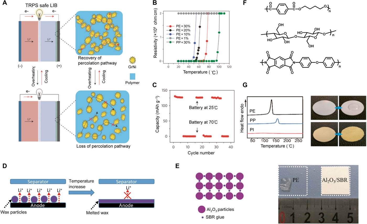 Fig. 5 Strategies to solve the issues in stage 2.
(A) Schematic illustration of the thermal switching mechanism of the TRPS current collector. The safe battery has one or two current collectors coated with a thin TRPS layer. It operates normally at room temperature. However, in case of high temperature or large current, the polymer matrix expands, thus separating the conductive particles, which can decrease its conductivity, greatly increasing its resistance and shutting down the battery. The battery structure can thus be protected without damage. On cooling, the polymer shrinks and regains the original conductive pathways. (B) Resistivity changes of different TRPS films as a function of temperature, including PE/GrNi with different GrNi loadings and PP/GrNi with a 30% (v/v) loading of GrNi. (C) Capacity summary of the safe LiCoO2 battery cycling between 25°C and shutdown. The near-zero capacity at 70°C indicates full shutdown. (A), (B), and (C) are reproduced with permission from Springer Nature. (D) Schematic representation of microsphere-based shutdown concept for LIBs. Electrodes are functionalized with thermoresponsive microspheres that, above a critical internal battery temperature, undergo a thermal transition (melt). The molten capsules coat the electrode surface, forming an ionically insulating barrier and shutting down the battery cell. (E) A thin and self-standing inorganic composite membrane composed of 94% alumina particles and 6% styrene-butadiene rubber (SBR) binder was prepared by a solution casting method. Right: Photographs showing the thermal stability of the inorganic composite separator and the PE separator. The separators were held at 130°C for 40 min. The PE significantly shrank from the area with the dotted square. However, the composite separator did not show obvious shrinkage. Reproduced with permission from Elsevier. (F) Molecular structure of some high-melting temperature polymers as separator materials with low high-temperature shrinkage. Top: polyimide (PI). Middle: cellulose. Bottom: poly(butylene) terephthalate. (G) Left: Comparison of the DSC spectra of the PI with the PE and PP separator; the PI separator shows excellent thermal stability at the temperature range from 30° to 275°C. Right: Digital camera photos comparing the wettability of a commercial separator and the as-synthesized PI separator with a propylene carbonate electrolyte. Reproduced with permission from the American Chemical Society.
Thermal shutdown separators. Another strategy to prevent batteries from thermal runaway during stage 2 is to shut down the conduction pathway of Li ions through the separator. Separators are key components for the safety of LIBs, as they prevent direct electrical contact between the high-energy cathode and anode materials while allowing ionic transport. PP and PE are the most commonly used materials, but they have poor thermal stability, with melting points of ~165° and ~135°C, respectively. For commercial LIB, separators with a PP/PE/PP trilayer structure have already been commercialized, where PE is a protective middle layer. When the internal temperature of the battery increases above a critical temperature (~130°C), the porous PE layer partially melts, closing the film pores and preventing migration of ions in the liquid electrolyte, while the PP layer provides mechanical support to avoid internal shorting . Alternately, thermally induced shutdown of LIB can also be achieved by using thermoresponsive PE or paraffin wax microspheres as the protective layer of the battery anodes or separators . When the internal battery temperature reaches a critical value, the microspheres melt and coat the anode/separator with a nonpermeable barrier, stopping Li-ion transport and shutting down the cell permanently (Fig. 5D).
Separators with high thermal stability. To improve the thermal stability of battery separators, two approaches have been developed during the past several years:
(1) Ceramic-enhanced separators, fabricated either by direct coating or on-surface growth of ceramic layers such as SiO2 and Al2O3 on existing polyolefin separator surfaces or by having ceramic powders embedded in the polymeric materials (Fig. 5E) , show very high melting points and high mechanical strength and also have relatively high thermal conductivity. Some composite separators fabricated through this strategy have been commercialized, such as Separion (a trade name).
(2) Changing the separator materials from polyolefin to high–melting temperature polymers with low shrinkage upon heating, such as polyimide , cellulose , poly(butylene) terephthalate, and other analogous poly(esters) , is another effective strategy for improving the thermal stability of separators (Fig. 5F). For example, polyimide is a thermosetting polymer widely regarded as a promising alternative because of its excellent thermal stability (stable over 400°C), good chemical resistance, high tensile strength, good electrolyte wettability, and flame retardancy (Fig. 5G) .
Battery packages with cooling function. Device-scale thermal management systems enabled by circulation of air or liquid cooling have been used to improve battery performance and slow down temperature increases. In addition, phase-change materials such as paraffin wax have been integrated into battery packs to act as a heat sink to regulate their temperature, therefore avoiding temperature abuse.
To solve the problems in stage 3 (combustion and explosion)
Heat, oxygen, and fuel, known as the “fire triangle,” are the necessary ingredients for most fires. With the accumulation of heat and oxygen generated during stages 1 and 2, the fuel (that is, highly flammable electrolytes) will automatically start to combust. Reducing the flammability of the electrolyte solvents is vital for battery safety and further large-scale applications of LIBs.
Flame-retardant additives. Tremendous research efforts have been devoted to the development of flame-retardant additives to lower the flammability of liquid electrolytes . Most of the flame-retardant additives used in liquid electrolytes are based on organic phosphorus compounds or organic halogenated compounds. As halogens are hazardous to the environment and human health, the organic phosphorus compounds are more promising candidates as flame-retardant additives because of their high flame-retarding ability and environmental friendliness. Typical organic phosphorus compounds include trimethyl phosphate, triphenyl phosphate , bis(2-methoxyethoxy)methylallylphosphonate , tris(2,2,2-trifluoroethyl) phosphite , (ethoxy)pentafluorocyclotriphosphazene , ethylene ethyl phosphate , etc. (Fig. 6A). The mechanism for the flame retardation effects of these phosphorus-containing compounds is generally believed to be a chemical radical-scavenging process. During combustion, the phosphorus-containing molecules can decompose to phosphorus-containing free-radical species, which can then terminate the radicals (for example, H and OH radicals) generated during chain reaction propagation that are responsible for continuous combustion (Fig. 6, B and C) . Unfortunately, the reduction in flammability with the addition of these phosphorus-containing flame retardants comes at the expense of electrochemical performance. To improve this trade-off, other researchers have made some modifications to their molecular structure: (i) partial fluorination of the alkyl phosphates can improve their reductive stability and their flame retardancy effectiveness ; (ii) the use of compounds having both protective film-forming and flame-retarding properties, such as bis(2-methoxyethoxy)methylallylphosphonate , where the allylic groups can polymerize and form a stable SEI film on graphite surfaces, thus effectively preventing hazardous side reactions; (iii) change of P(V) phosphate to P(III) phosphites, which facilitate SEI formation and are capable of deactivating hazardous PF5 [for example, tris(2,2,2-trifluoroethyl) phosphite]; and (iv) replacing organophosphorus additives with cyclic phosphazenes, especially fluorinated cyclophosphazene, which have enhanced electrochemical compatibility .

Fig. 6 Strategies to solve the issues in stage 3.
(A) Typical molecular structures of flame-retardant additives. (B) The mechanism for the flame retardation effects of these phosphorus-containing compounds is generally believed to be a chemical radical-scavenging process, which can terminate the radical chain reactions responsible for the combustion reaction in the gas phase. TPP, triphenyl phosphate. (C) The self-extinguish time (SET) of the typical carbonate electrolyte can be significantly reduced with the addition of triphenyl phosphate. (D) Schematic of the “smart” electrospun separator with thermal-triggered flame-retardant properties for LIBs. The free-standing separator is composed of microfibers with a core-shell structure, where the flame retardant is the core and the polymer is the shell. Upon thermal triggering, the polymer shell melts and then the encapsulated flame retardant is released into the electrolyte, thus effectively suppressing the ignition and burning of the electrolytes. (E) SEM image of the TPP@PVDF-HFP microfibers after etching clearly shows their core-shell structure. Scale bar, 5 μm. (F) Typical molecular structures of room temperature ionic liquid used as nonflammable electrolytes for LIBs. (G) The molecular structure of PFPE, a nonflammable perfluorinated PEO analog. Two methyl carbonate groups are modified on the terminals of polymer chains to ensure the compatibility of the molecules with current battery systems.
It should be noted that there is always a trade-off between the reduced flammability of the electrolyte and cell performance for the additives listed, although this compromise has been improved through the above molecular designs . Another proposed strategy to solve this problem involves incorporating the flame retardant inside the protective polymer shell of microfibers, which are further stacked to form a nonwoven separator (Fig. 6D) . A novel electrospun nonwoven microfiber separator with thermal-triggered flame-retardant properties was fabricated for LIBs. The encapsulation of the flame retardant inside the protective polymer shell prevents direct exposure of the flame retardant to the electrolyte, preventing negative effects from the retardants on the electrochemical performance of the battery (Fig. 6E). However, if thermal runaway of the LIB battery occurs, the poly(vinylidenefluoride-hexafluoro propylene) copolymer (PVDF-HFP) shell will melt as the temperature increases. Then the encapsulated triphenyl phosphate flame retardant will be released into the electrolyte, thus effectively suppressing the combustion of the highly flammable electrolytes.
A “salt-concentrated electrolyte” concept was also developed to resolve this dilemma . These fire-extinguishing organic electrolytes for rechargeable batteries contain LiN(SO2F)2 as the salt and a popular flame retardant of trimethyl phosphate (TMP) as the sole solvent. The spontaneous formation of a robust salt-derived inorganic SEI on the anode is crucial for stable electrochemical performance. This novel strategy can be extended to various other flame retardants and may open a new avenue for developing new flame-retardant solvents for safer LIBs.
Nonflammable liquid electrolytes. An ultimate solution to the safety issues of the electrolyte would be to develop intrinsically nonflammable electrolytes. One group of nonflammable electrolytes that has been extensively studied is ionic liquids, especially room temperature ionic liquids, which are nonvolatile (no detectable vapor pressure below 200°C) and nonflammable and have a wide temperature window (Fig. 6F) . However, continuous research is still required to solve the issues of low rate capability arising from their high viscosity, low Li transference number, cathodic or reductive instability, and the high cost of ionic liquids.
Low-molecular weight hydrofluoroethers are another class of nonflammable liquid electrolytes because of their high or no flash point, nonflammability, low surface tension, low viscosity, low freezing temperature, etc. . Proper molecular design should be made to adapt their chemical properties to meet the criteria of battery electrolytes. An interesting example that has been recently reported is perfluoropolyether (PFPE), a perfluorinated polyethylene oxide (PEO) analog that is well known for its nonflammability (Fig. 6G) . Two methyl carbonate groups are modified on the terminal groups of PFPE chains (PFPE-DMC) to ensure the compatibility of the molecules with current battery systems. Thus, the nonflammability and thermal stability of PFPEs can improve the safety of LIBs significantly while increasing the electrolyte transference number due to the unique molecular structure design.
Stage 3 is the final but particularly crucial stage for the thermal runaway process. It should be noted that although great efforts have been devoted to reducing the flammability of the state-of-the-art liquid electrolyte, the use of solid-state electrolytes that are nonvolatile shows great promise. Solid electrolytes mainly fall into two categories: inorganic ceramic electrolytes [sulfides , oxides, nitrides , phosphates, etc.] and solid polymer electrolytes [blends of Li salts with polymers, such as poly(ethylene oxide), polyacrylonitrile, etc.] . Efforts to improve solid electrolytes will not be detailed here, as this topic has already been well summarized in several recent reviews .
OUTLOOK
In the past, many novel materials have been developed to improve battery safety, although the problem has not yet been entirely solved. In addition, the mechanisms underlying safety issues vary for each different battery chemistry. Thus, specific materials tailored for different batteries should be designed. We believe that more efficient methods and well-designed materials remain to be discovered. Here, we list several possible directions for future battery safety research.
First, it is important to develop in situ or in operando methods to detect and monitor the internal health conditions of LIBs. For example, the thermal runaway process is closely related to the internal temperature or pressure increase within LIBs. However, the temperature distribution inside batteries is rather complex, and methods are needed to precisely monitor the values for electrolytes and electrodes, as well as separators. Thus, being able to measure these parameters for different components is critical for diagnosing and thus preventing battery safety hazards.
The thermal stability of separators is crucial for battery safety. The newly developed polymers with high melting points are effective at increasing the thermal integrity of the separator. However, their mechanical properties are still inferior, greatly reducing their processability during battery assembly. Moreover, price is also an important factor that should be considered for practical applications.
The development of solid electrolytes seems to be the ultimate solution for the safety issues of LIBs. The solid electrolyte will greatly reduce the possibility of battery internal shorting, along with the risk of fires and explosions. Although great efforts have been devoted to the advancement of solid electrolytes, their performance continues to lag far behind that of liquid electrolytes. Composites of inorganic and polymer electrolytes show great potential, but they require delicate design and preparation. We emphasize that proper design of the inorganic-polymer interfaces and engineering of their alignment are crucial for efficient Li-ion transport.
It should be noted that the liquid electrolyte is not the only battery component that is combustible. For example, when LIBs are highly charged, the combustible lithiated anode materials (for example, lithiated graphite) are also a big safety concern. Flame retardants that can efficiently retard fires of solid-state materials are highly demanded to increase their safety. The flame retardants may be mixed with the graphite in the form of polymer binders or conductive frameworks.
Battery safety is a rather complex and sophisticated problem. The future of battery safety calls for more efforts in fundamental mechanistic studies for deeper understanding in addition to more advanced characterization methods, which can offer further information to guide materials design. Although this Review focuses on materials-level safety, it should be noted that a holistic approach is further needed to solve the safety issue of LIBs, where materials, cell components and format, and battery module and packs play equal roles to make batteries reliable before they are released to the market.
REFERENCES AND NOTES
Kai Liu, Yayuan Liu, DingchangLin, Allen Pei, Yi Cui, Materials for lithium-ion battery safety, ScienceAdvances, DOI:10.1126/sciadv.aas9820
Post time: Jun-05-2021